This article provides you details about the dimensional requirements in pressure vessel construction and pressure vessel inspection. ...

This article provides you details about the dimensional requirements in pressure vessel construction and pressure vessel inspection.
As we discussed in the ASME Code Section VIII simplified article, some of the fabrication tolerances have not been addressed in ASME Code Section VIII Division 1. So, you may need to refer, other sources for that tolerances while inspection. ASME Section VIII describes that “When dimensions, sizes, or other parameters are not specified with tolerances, the values of these parameters are considered nominal, and allowable tolerances or local variances may be considered acceptable when based on engineering judgment and standard practices as determined by the designer”. This article provides you the most important dimensional inspection requirements and which are the tolerances not addressed in Section VIII Division 1? In such cases What is the standard practices acceptable in the industry as well as the designer/user of the pressure vessel. In this article Pressure Vessel Handbook 12th Edition written by Mr. Eugene F. Megyesy is used as the standard practice for inspection tolerances that are not addressed in ASME Section VIII Division 1.
This article based on my understanding of Section VIII Division 1 and experience. Your comments and advice are highly appreciated. Let’s enter in the article, the dimensional check of a pressure vessel consists of the following items:
- Mill Under tolerance of Plates and Pipes
- Tolerances for Formed Heads
- Out of Roundness of shell
- Nozzles and attachments Orientation
- Nozzles and attachments Projection
- Nozzles and attachments elevation
- Nozzles and attachments levelness
- Weld mismatch
- Weld reinforcement
Mill Under tolerance of Plates and Pipes
Dimensional Inspection of Plate
Your pressure vessel plates with 0.01 inch (0.3mm) or 6% under tolerance, whichever is smaller, may be used for full design pressure, instead of at the given design thickness specified.
However, if the material specification allows greater under tolerance, then the ordered thickness for the material should be sufficiently greater. An example, if you have SA 516 Gr.70 plate with a 0.625inch nominal thickness, and the actual thickness is 0.615, it is acceptable, and you may use this plate without any specific design consideration. But, if the same plate has an actual thickness of 0.595 inches, you need to consider mill under tolerance in your design calculation.
This plate thickness is acceptable based on the material specification (see the table in SA 20 for thickness tolerances). We cannot reject this plate unless otherwise specifically instructed in the material requisition or purchase order because it is in the permissible tolerance of plate specification. But as per the ASME Code Section VIII Division 1, you need to consider this 0.03 inches in your design calculation: e.g. Thickness = Min Thickness + Corrosion Allowance + Mill Under tolerance
Dimensional Inspection of Pipe
Contrary to the plate material, your pipe and tube mill under tolerances need to be taken into account for design consideration. Pipe and tube under tolerances are almost -12.5 % of the nominal wall thickness, but sometimes there are differences for different materials, so for any specific material, it shall be referred to the suggested pipe or tube material specification to obtain the exact amount of mill under tolerances.
An example, if there is a pressure vessel with a nominal shell thickness of 0.5 inches, it needs a 6” SA 106 Gr B nozzle to be attached to the shell plate. Assume that external loading is not a design controlling factor, hence our minimum, nozzle thickness will be the same as the shell thickness. With the consideration of under tolerance -12.5%, the pipe selection will be 0.5 + 12.5% = 0.625 inches and as per the ASME B36.10, our pipe schedule will be SA 106 Gr B Schedule 160.

Dimensional Inspection - Tolerances for Formed Head
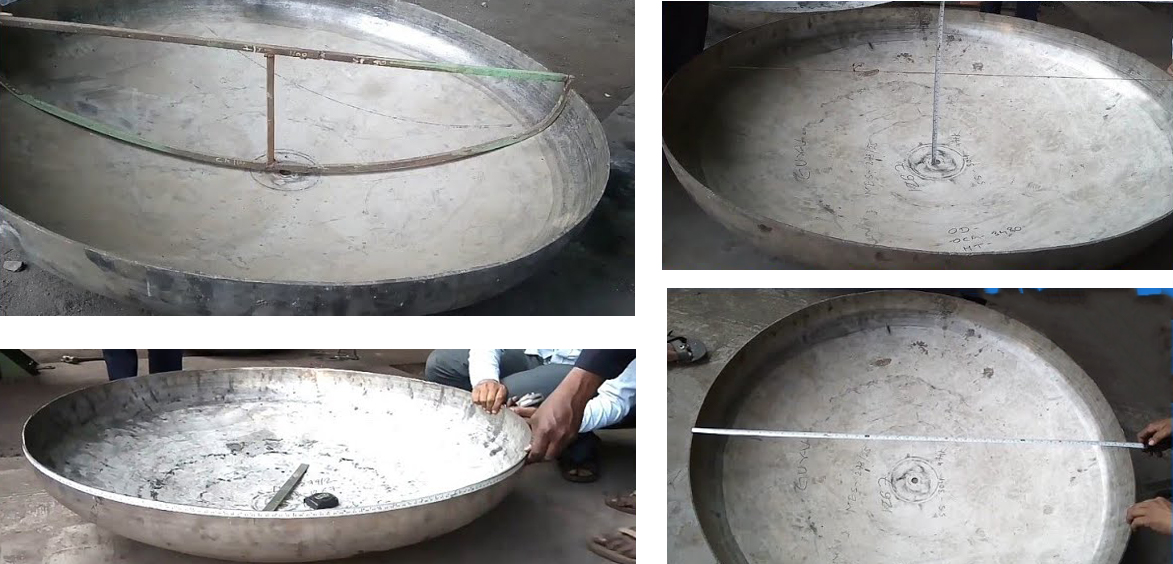
You may know that there is a specific rule for dimensional checking of formed heads, based on the UG-81, the inner surface shall not deviate outside of the specified shape more than 1¼% of D and inside the shape more than 5/8% of D (D is the nominal inside diameter of the vessel shell at the point of attachment)
You can use sweep boards, which are made by cutting a thin steel sheet or piece of wood for checking your crown and knuckle radius. The skirt, the difference between the maximum and minimum inside diameter, shall not be more than 1%, and you can use a measuring tape or laser distance meter for dimensional control of the skirt.
An example, we check the following head which will help you fully understand:
Head ID = 3300 mm
Nominal thickness = 20 mm
Head Type: Torispherical
As per ASME Section VIII permitted tolerance for outside of the specified shape = 3300 x 1¼% = 41.25 mm
As per ASME Section VIII permitted tolerance for the inside of the specified Shape = 3300 x 5/8% = 20.625 mm
We checked the depth, and the drawing is 630 mm and the actual is 643 mm, so it is outside of the shape. We need to verify, is it within the range of tolerance? As we calculated above the acceptable maximum outside of the shape can be 41.25 + 630 = 671.25, our actual value is 643 mm which is less than 671.25. So, it is compliance with ASME Section VIII Division 1, UG-81 requirements.


We need two sweep boards to verify the radius of the head crown and knuckle. We can make it from a thin steel sheet or wooden piece one with the radius of the head drawing crown radius of 3300 mm and the other one for the knuckle radius of 200 mm. We check the above head with the sweep boards. The sweep board should fit properly in the crown and knuckle radius and the edge distance to the head surface should not deviate from the above-limited values.
The Skirt out of roundness maximum and minimum ID should not be more than 1% of the ID, which is 33 mm. So, in the above example roundness also acceptable. Our nominal thickness is 20 mm, so up to 19.70 (tolerance 20 mm – 0.3 mm) is acceptable for the above example. So, this head is in compliance with the code requirements.
Importance note, the out of roundness (ovality) tolerance 33 mm specified only the difference between the minimum and maximum diameter measurement of the head edge which will be welded with the shell. It does not mean a 33 mm increase in diameter. Just imagine, the shell is an exact diameter of 3300mm and the head is 3333mm when fit-up it together for welding how much hi-low will come.
So, my advice for a practical solution for the above, please check the circumference (Periphery) of the shell and respective head, then check the diameter the difference between them, it should be the acceptable hi-low limit.
Dimensional Inspection of Shell (Out of Roundness)
UG-80 deals with out of roundness of shell. The maximum permitted ovality tolerance (D max – D min) shall not exceed 1% of the nominal diameter of the vessel.
If you have an opening, then the tolerance can be increased by 2% x d (d = diameter of the opening), if the measurement is taken within a distance of "d" from the axis of the opening.
The out of roundness generally is measured in minimum two directions with a normal measuring tape or laser distance meter, so one direction would be the D max and the other one would be the D min.
The below picture shows an out of roundness measurement:

Dimensional Inspection of Nozzles and Attachments Orientation
ASME Code SEC VIII Division 1 has not specified the orientation tolerances for nozzles and attachments, hence you need to refer the pressure vessel handbook which is generally accepted as standard practice in the oil & gas industry.
As per the pressure vessel handbook, it is ±½ degree. The orientation can be checked by a simple calculation by using a measuring tape in the actual measurement work on the vessel.
An example, we want to check the N1 nozzle orientation in the below drawing.

The nozzle N1 is located at 45 degrees in the drawing. The manufacturer has located this point in the vessel with a marker, and we want to verify the location, and if it is correct, then we can allow the manufacturer to cut.
To verify the above marking we do a simple calculation:
Pressure Vessel OD as per drawing is = 2000mm
Shell outside Circumference length is = π x OD = 3.142 x 2000 = 6284mm
It means this pressure vessel circle’s 360 degrees is 6284mm, hence each degree represents 6284/360=17.455mm
As per the above drawing location of N1 is 45degree, so it will be 45 x 17.455 = 785.475mm. Now we use a measuring tape and keep the 0 at the zero-reference point in the vessel and pull the tape to the nozzle center mark and note the reading.
As we discussed above, nozzle orientation tolerance is ±0.5 degrees. In our case, the tolerance will be 17.455 x 0.5 = 8.7mm plus or minus from the above calculated 45degree measurement of 785.475mm. So, if the above reading lays between the following range (776.775 ~ 794.175), then the marking is acceptable and we can approve to cut the opening.
785.475 – 8.7mm = 776.775mm
785.475 + 8.7mm = 794.175mm
Important notes: Measuring tape’s least count is 1mm, so always round off the figures to the nearest whole number. Same as the above roundness inspection, you should check the actual circumference dimension of the vessel prior to the calculations. If the actual circumference differs from theoretical, use the actual measurement for calculations.
Dimensional Inspection of Nozzles and Attachments Projection
Nozzle and attachment projection is the length from the nozzle or the attachment face to the vessel shell centerline. Projection dimensions are addressed either in general assembly drawings or nozzle/attachment detail drawing. The projection tolerances are not addressed in ASME Code Section VIII Division 1, you can refer the pressure vessel handbook, according to it ± 0.25 inch (6mm) is permissible.
In the above vessel GA drawing, we need to check the N1 nozzle projection. It should be 200 mm in distance from the shell to the flange face (shortest distance from the outside surface of the vessel to the face of the nozzle). Refer to the highlighted portions of the below picture.

You may use a measuring tape or ruler to measure the distance between the shell outside circumference to the nozzle face. In our case, N1 nozzle projection is 200 mm and the tolerance is ±6 mm, hence your reading should be between 194 to 206 mm. Then, the nozzle projection is acceptable.
Dimensional Inspection of Nozzles and Attachments Elevation
Nozzles and attachments elevation is the length between the nozzles or the attachments centerline (some cases it will be top of the nozzle e.g vertical nozzles) and the bottom or top head tangent line. The elevation dimension is addressed directly in the general assembly drawing or detail drawing of nozzles. Same as orientation, the ASME Code Section VIII Division 1 doesn’t address the elevation tolerances. According to the pressure vessel handbook, ±0.25 inch (6 mm) is permissible for nozzle elevation.
Now, we check the nozzle N1 elevation of the same pressure vessel. As you see in the drawing, the distance between the nozzle centerline to the bottom head tangent line is 150 mm.

The easy practical approach you can measure from the bottom of the nozzle neck to bottom head tangent line and add the radius of the nozzle neck to get the nozzle centerline measurement. Our acceptable range for N1 elevation is 144 to 156 mm (150-6=144 & 150+6=156). Hence, if the measurement lays between 144 to 156mm, then the nozzle elevation is acceptable.
Dimensional Inspection of Nozzles and Attachments Levelness
The nozzles and attachments levelness tolerances are not addressed in ASME Code Section VIII Division 1, but in the pressure vessel handbook, a ½˚ deflection is permissible. The levelness can be checked with a level gage. If you are using the bubble spirit level and the bubble is in the middle of the designated lines, then the nozzle is level. It shall be checked in two directions in 90 degrees apart.
If the bubble intersects the designated limit lines, you need to do a simple calculation and see if your deflection is within the tolerance limit. You need to move one end of the bubble spirit level up to the bubble to be placed in the middle. Then measure the distance between the level gage end and the flange face. The measured value is “a” in the figure.

Then obtain θ, if θ is less than 0.5˚, the deflection falls within the tolerances, and it is acceptable otherwise it will require rectification to bring within the acceptable limit. It may require cutting and rewelding.
Dimensional Inspection of Weld Mismatch
ASME Code Section VIII Division 1 specified tolerances for weld mismatch in UW-33. It is important to know that the limit for weld mismatch is stringent for a category A weld (Longitudinal joint and circumferential shell to hemispherical head). The concept behind this is that the longitudinal joint bears double the amount of stress, and inspectors should take extra care in checking these joints.
An example, you have a pressure vessel with a nominal thickness of 1 inch. You do a visual and measure the mismatch by the welding gauge (Camgauge). Assume you found a 0.143inch mismatch in one longitudinal and one circumferential joint. Look into the UW-33 table

The permissible weld mismatch in the longitudinal joint for your case is 0.125 of an inch and for the circumferential joint, it is 0.1875 of an inch. Your weld mismatches for both longitudinal and circumferential joints are 0.143, so your circumferential joint is acceptable, but your longitudinal joint should be repaired.
As a proactive measure, in your practical work to avoid this situation and weld repair, you should control the hi-low during the fit-up inspection.
Dimensional Inspection of Weld Reinforcement
The same concept for weld mismatch exists for weld reinforcement tolerances. The longitudinal joint weld reinforcement limit is more stringent than that for circumferential joints. This is because longitudinal joint bears double stress, and it is required that the stress concentration is minimized.
In the above example joints, assume that there are 0.150 of an inch welds reinforcement for both category A and B welds. You can find the acceptance limit for weld reinforcement in the ASME Section VIII Division 1, UW-35. See below picture for reference

As per Section VIII Division 1, UW-35, Category A allowance is 0.0937 inch and Category B allowance is 0.1875. So, the circumferential joint reinforcement is acceptable, but the longitudinal joint reinforcement is unacceptable and should be repaired by removing the excess weld reinforcement. When grinding the excess weld metal, must take care in the weld profile, it should be smooth without any sharp notches, no open discontinuities, good weld toe transition and parent metal thickness shall not be reduced.
Conclusion
This article describes the dimensional inspection requirements and method of inspections, calculation of tolerances, and the industry-accepted standard practices for pressure vessel inspection. It may help you in the pressure vessel inspection according to ASME Section VIII Division 1. But remember, this is not a reference document for your inspections, please always refer to ASME Section VIII, your project specifications, procedures, method statements, and quality requirements of your company.
No comments